Working board and audio
Bringing up the new board this time was pleasantly straight forward.
I did have one mistake on the design where the enable lines for the data bus buffers were using LDS and UDS which would have caused some major bus contention issues when reading any data.
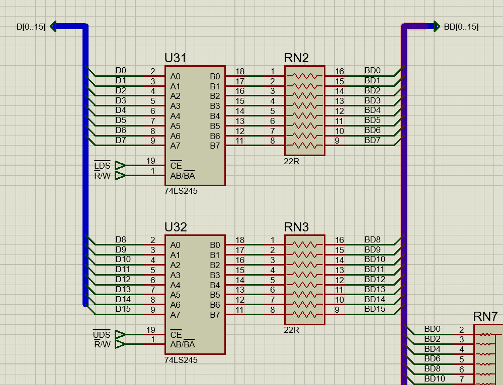
I avoided that problem thanks to eagle eyes of Laurance Manning who has designed his own 68000 based computer the MAXI000. He saved me some considerable time scratching my head while trying to work out why it wasn’t booting. Fixing the issue was dony by cutting the tracks to the enable pins and connected them to some spare pins on the CPLD so now the data lines for the bus are only enabled when the expansion bus is accessed.
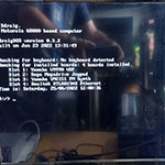
With the board modifications done, the CPLD was updated with the changes and I powered on the board. The board started up and I was greeted with a prompt on the serial terminal so the monitor code was running. With the monitor working I ran tests on the DRAM and the IDE and they were also seem to be working fine. While I had expected things to go fairly easy as there wasn’t any major changes in the main design over the last revision of the board but still a bonus to get things up and running so quickly.
Testing the expansion bus
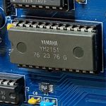
With the main board working it was time to move on and start testing the expansion bus. Running some simple tests and measuring on the scope showed that the basic access to the bus was working correctly, the CS and ID lines as well as the signal lines all seemed to be correct. To test the bus properly I had already designed a sound card based around the YM2151. The design was based on the one that I had working successfully on the previous revision of the board.
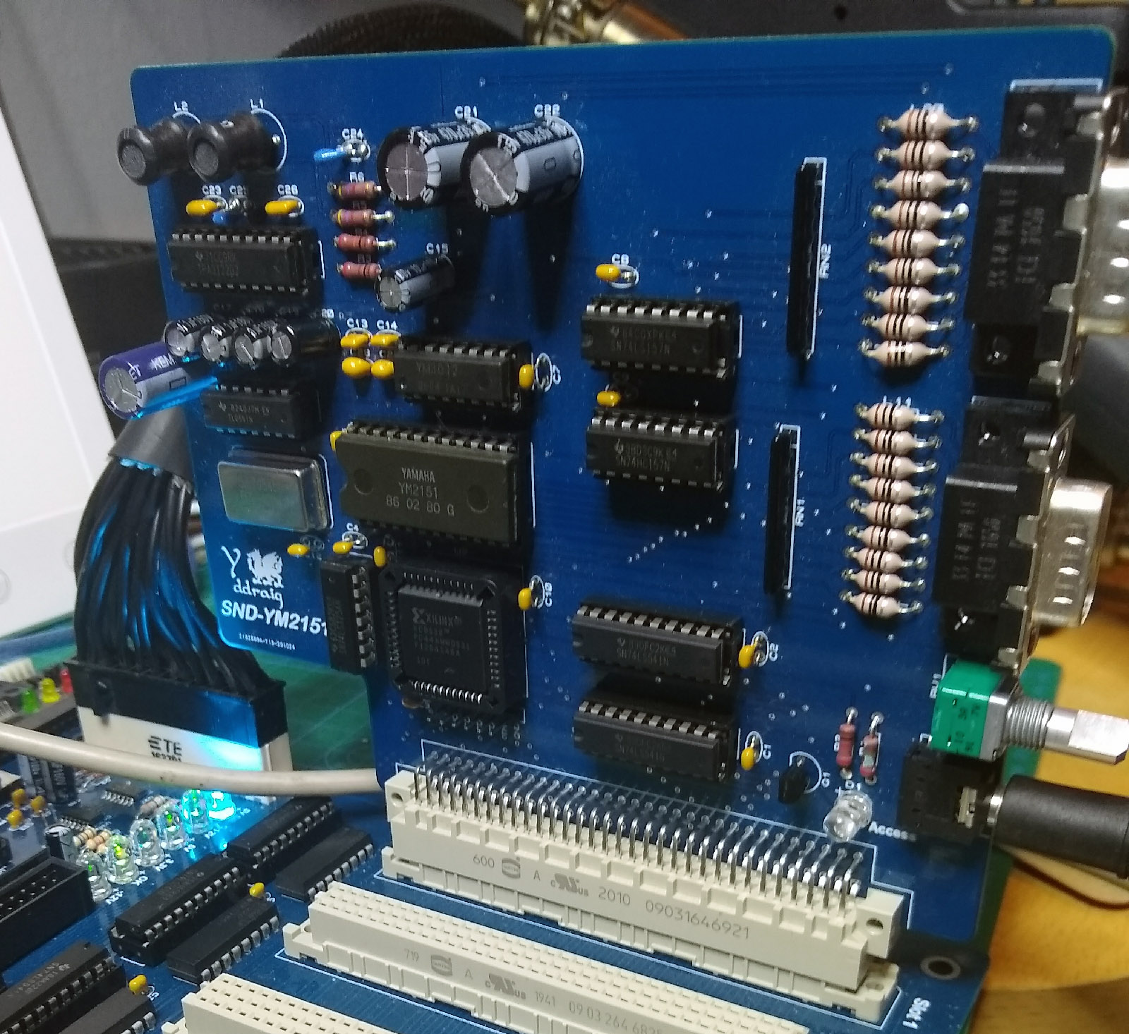
On the expansion boards there are two memory ranges for accessing them. For expansion slot 1 the access is at a 256 ID range to identify the boards and possibly for control in the future. The other address is a 1M address range for accessing the board directly. On the YM2151 the 1M range is overkill as only a couple of bytes are needed for register access so I could easily map it all into the 256 byte ID range and may change this in the future. The entire ID range is currently used to read an address hardcoded on a 74LS541 buffer with the enable on the ID line.
The first test with the audio board was to use the monitor to read the address at 0xf8f500 and this returned the correct value. I tested the board by modifying the VGM Rip player I used for testing previously. This took a little while to get up and running but that was down to some errors in my CPLD code. I managed to get that resolved and within a few hours and had working sound card. There are two joystick ports on the board which are currently untested but the purpose of the board was to test if the expansion bus will work and that’s been a success.
Here’s a capture of the X68000 version of the Space Harrier theme captured directly from the card.
Getting both boards working was easier than I had anticipated but I think that was largely due to the design had been proven on my previous revision so the work done there was not a complete waste at least.
Video and OS
There are two big steps that are needed next, one is getting a video board up and running and getting a working operating system.
Longer term I’m looking at a solution using an FPGA with at least VGA output. Until then time I have a board design based on the v9958 that I need to built up and get tested.
The main focus for now will be on getting a basic operating system up and running. My current development process is to write the software on the PC and transfer code in Motorloa S-Record format. While this process isn’t too bad for smaller programs, some of the sound test programs can take several minutes to download. At the very least I need to be able to load programs from disk.